

Site selection and site analysis
Uncover high-potential sites faster and smarter

Deliver faster, more accurate solar projects from site selection, to design, and yield estimation

Beyond surface-level screening for buildable, power-ready sites

The next era of solar belongs to the teams that bridge the systemic gaps between plan and execution.
Nearly 80% of PV projects end up in the shade. PVcase turns obstacles into opportunities, securing economic and sustainable success at every stage.

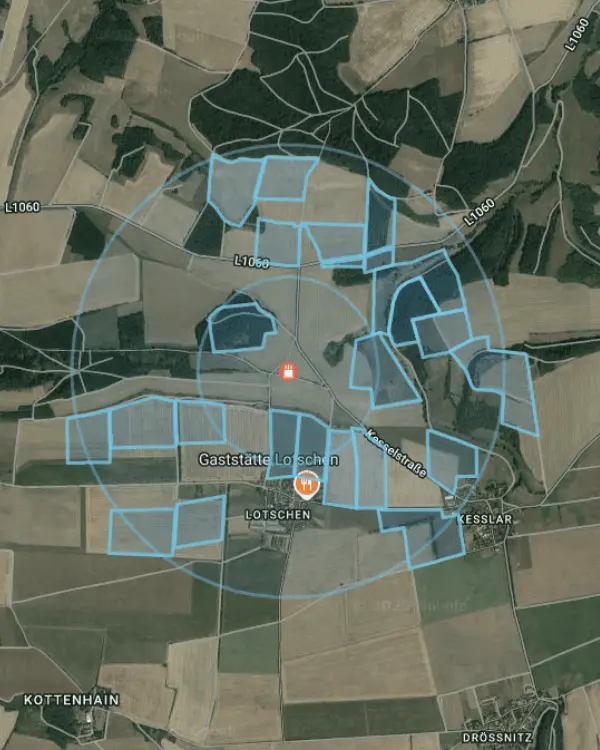
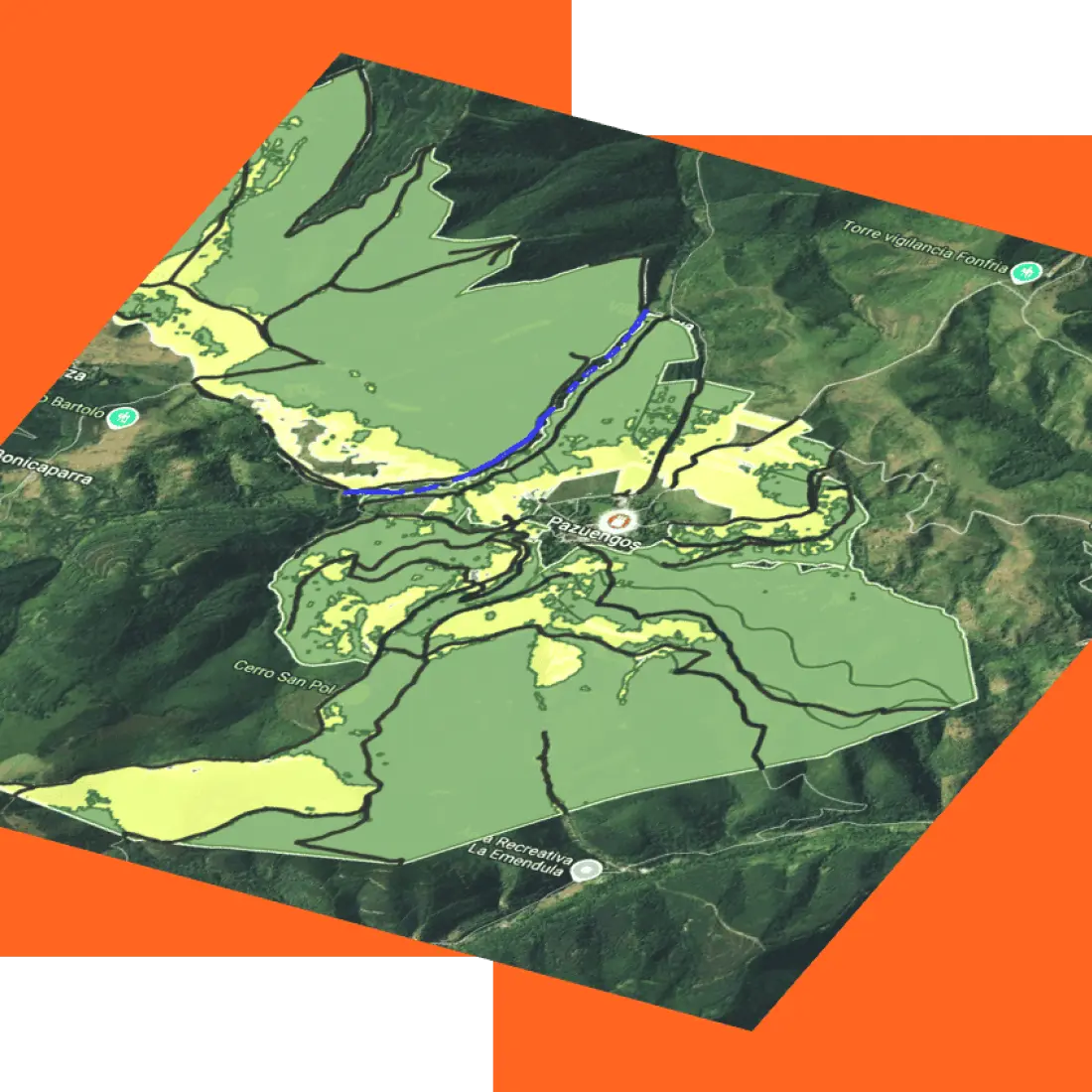
De-risk site selection and enhance early-stage project development due diligence efforts with PVcase Prospect. Stop juggling disconnected tools. Analyze land around the right POIs and uncover the best sites for your projects in minutes – all in one cloud-based platform.

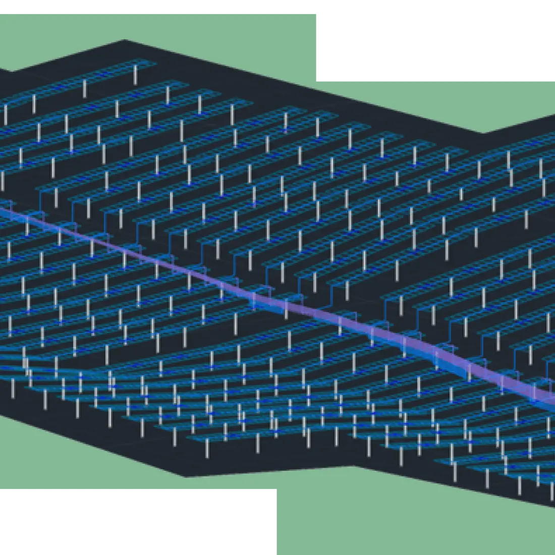
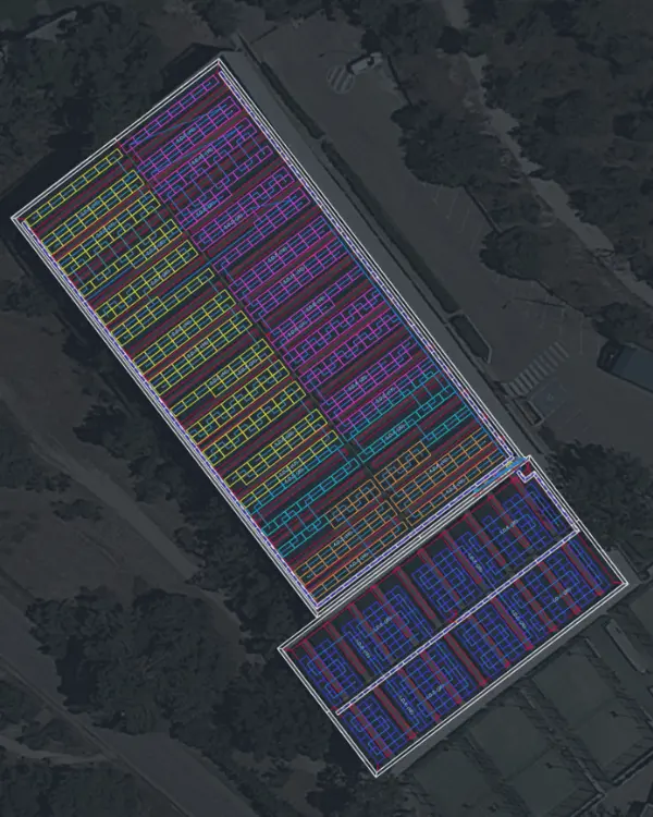
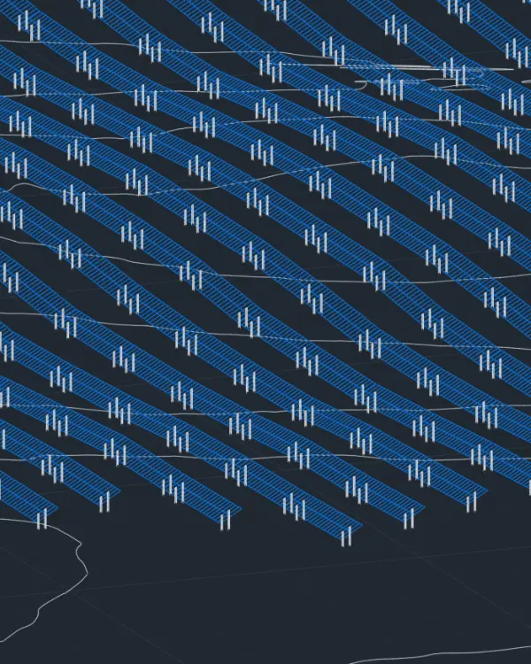
Design construction-ready projects 90% faster. PVcase Ground Mount, built on AutoCAD, automates utility-scale solar design, adapting complex layouts to real-word terrain with unmatched accuracy.

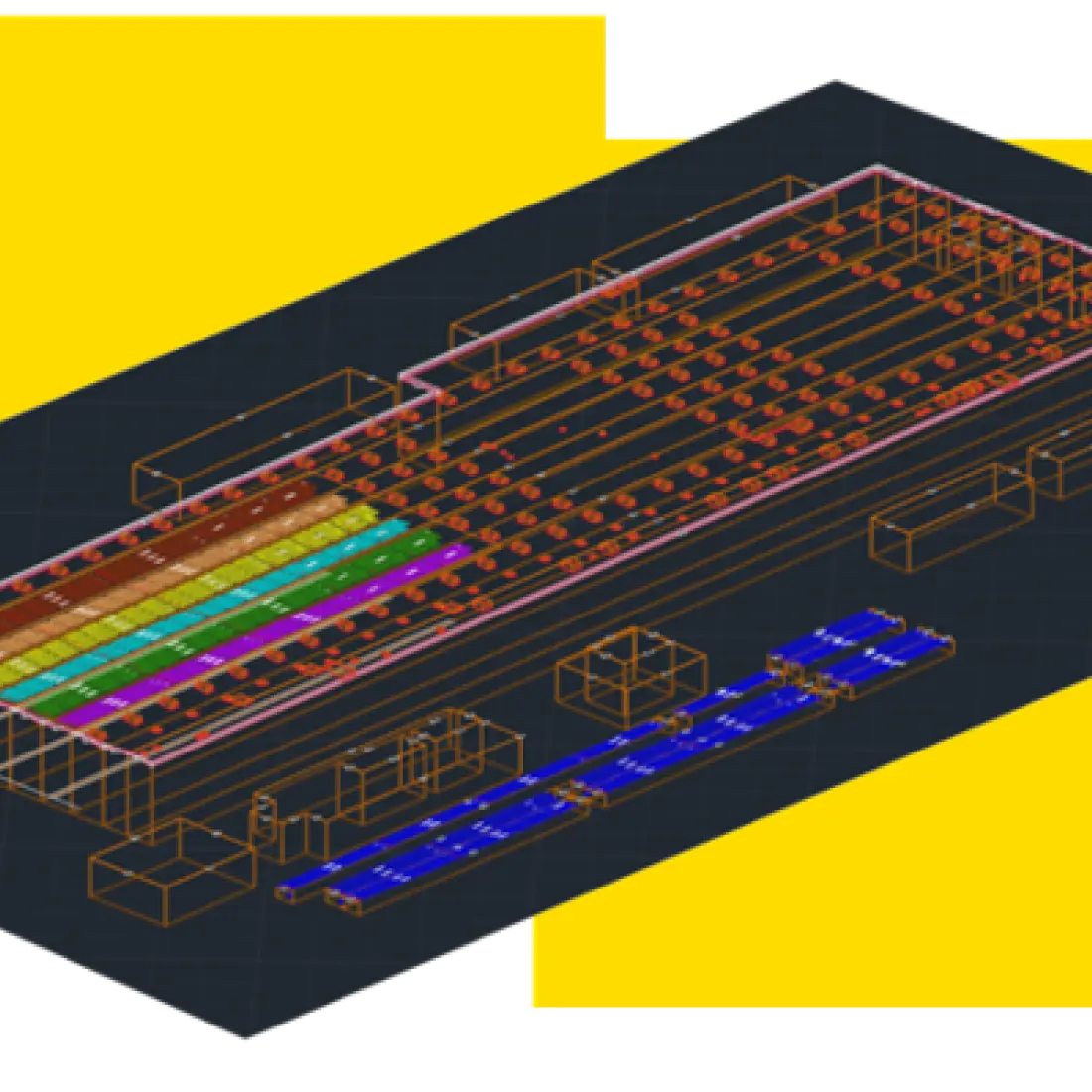
Revamp complex rooftops into powerhouse solar assets. PVcase Roof Mount delivers rapid, precise automated designs, accelerating approvals and project execution.

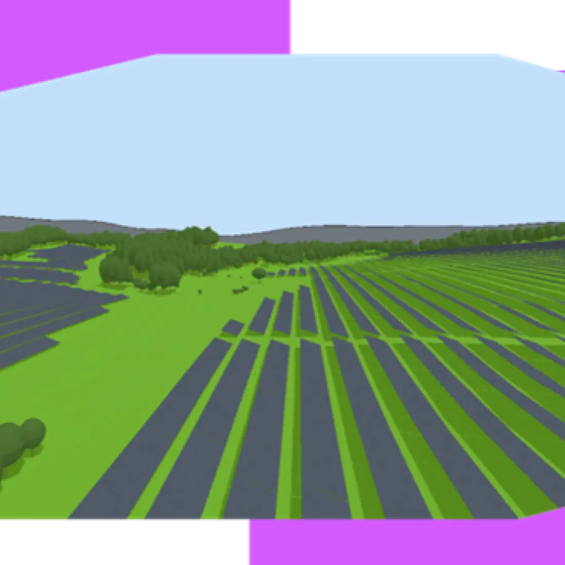
Model with certainty, not guesswork. Connect with PVcase Yield for robust energy modeling, providing crystal-clear insights that strip away risk.
Uncover high-potential sites faster and smarter
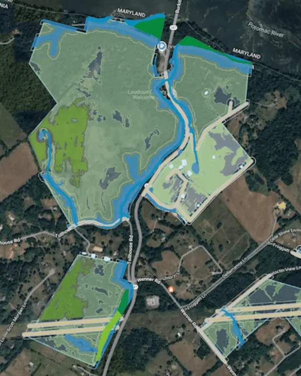
Move first on top data center sites using an automated process
Design C&I rooftops faster, smarter, more profitably
Deliver solar projects with speed and unprecedented accuracy
Peter Knittl
CEO
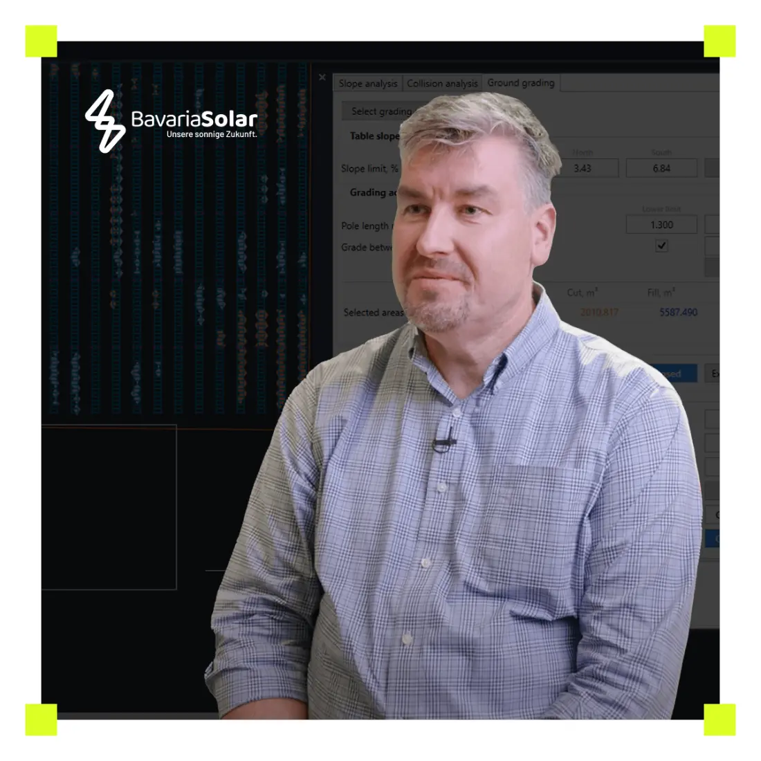
Sergio de la Torre
Strategic Transactions Engineering Lead

Hannes Elsen
Engineering Team Lead


Turn complexity into clarity and confidently move your solar project forward.