Complex MV Designs


PVcase allows to easily create MV Circuits in a linear or loop fashion. When more complex designs are needed with multiple interconnection bays at the POI, MV Junction Boxes or Y branches at certain Transformers, then some workarounds need to be used.
1. Multiple MV bays at Grid Connection Point
One Grid Connection point cannot directly host multiple MV branches. The workaround in this case is very simple: Create multiple, one Grid Connection points for each MV circuit connecting to the Substation. Each one of these Grid Connections can be colocated and considered a Substation Bay.
The Overview will still show the Bays as Grid Connections, but the number label in the Model Space can be modified to include “Substation Bay”.
The Single Line Diagram will now also show the new labels (but the user can further edit these by exploding the SLD), and the cable lengths for all three MV Circuits will be calculated correctly with this design.
The exported BOM Excel file showing the adequate lengths can also be post-edited to show the proper naming convention.
2. Y branching at MV Dead Break Junction Boxes
Dead Break Junction Boxes are used to combine two or more MV lines into one. These are common when multiple MV lines converge at a certain location and from there go to the Substation. In order to generate an MV paralleling Junction Box, the designer will need to use the Grid Connection feature. The workaround in this case consists in generating a “Transformer” in the location where the Junction Box is to be placed, and then create two or more Grid Connection points from there out.
The Overview will still show the Junction Box as a “Transformer” (16 in the GIF) and the Junction Box Bays as Grid Connections (3 and 4 in the GIF), but in the Model Space the number labels for the "Transformer” and Grid Connections can be modified to show “Junction Box” and “JB Bay” respectively.
The Single Line Diagram will now also show the new labels (but the user can further edit these by exploding the SLD) and the cable lengths for all MV Branches will be calculated correctly with this design.
The exported BOM Excel file showing the correct lengths can also be post-edited to show the proper naming convention.
3. Y branching at MV Transformers
It is common to have two incoming (and one outgoing) MV voltage feeders at certain MV skid transformers. PVcase Transformers can only be linked in an open or closed MV line, but not branch out into two or more MV lines. The workaround in this case starts by creating main lines of transformers all the way to the Substation Bay.
Then add a “Grid Connection” at the specific transformers for each extra branch that is needed.
The Overview will still show the extra branches as Grid Connections, but the “Grid Connection” number label in the Model Space can be moved, eliminated or modified to show “XFR Branch”.
The Single Line Diagrams will now also show the new labels (but the user can further edit these by exploding the SLD) and the cable lengths for all MV Branches will be calculated correctly with this design.
The exported BOM Excel file showing the correct lengths can also be post-edited to show the proper naming convention.
4. Transformer with multiple co-located Central Inverters
Because of the ever-increasing size of PV Transformer blocks and the limited MW capacity of commercially available Central Inverters, most MV skids/containers are comprised of more than one co-located Central Inverter. This has multiple benefits like more MPPTs, higher reliability and more space for DC inputs.
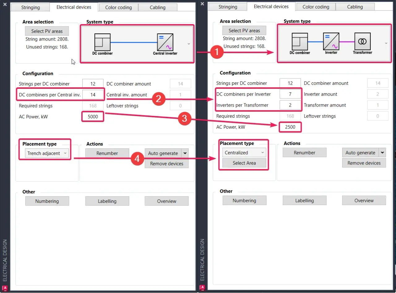
It is possible to design such systems with PVcase, but instead of using the standard “DC Combiner - Central Inverter” system type, the user would select “DC Combiner - Inverter - Transformer” (step 1). The quantities selected in the Configuration section would be based on the original numbers, but divided among the co-located Central Inverters (steps 2 and 3). And the Placement type would be changed from “Trench adjacent” to “Centralized” (step 4):
Now that the settings are defined, the user can generate the Electrical devices, selecting which strings are to be linked to a certain inverter (or allowing the software to assign these automatically):
The new block generated in this fashion will show in the Overview and in the SLD as a Transformer with two (or more) inverters associated to it:
Now, DC and HV cabling can be generated as normally done, but we can now also add the AC cabling at Skid/container if needed: