The many uses of Terrain Mesh

As referenced in multiple tutorials and release notes, the PVcase Terrain Mesh instrument has multiple potential uses.
In order to get acquainted with how it works, it is best to start by checking out this detailed Terrain Mesh tutorial.
In this article, we present 8 of the most useful ways to employ this tool:
- Terrain visualization
- Checking for topographical layer issues
- Creating offsets
- Overlapping offsets
- Changing offset layer
- Checking shadow frames
- Comparing Mesh before and after grading
- Exporting to PVsyst
1. Terrain visualization
The most common use for a mesh is to better see what the terrain looks like. The selected topography to be used with PVcase can take many forms (check out this article for more information on this) but in most cases, they don’t allow the designer to easily interpret the terrain. Creating a Mesh allows the user to understand what the terrain looks like in order to make appropriate design decisions.
The Slope table setup section allows the user to quickly customize the number and size of the slope ranges.
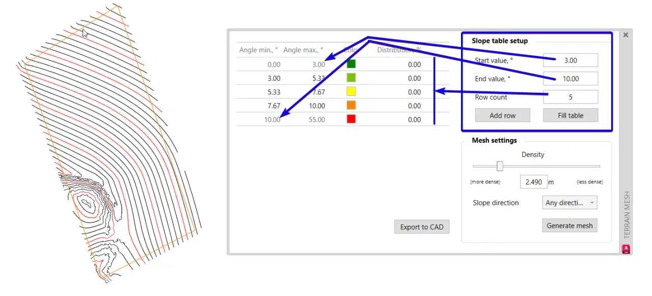
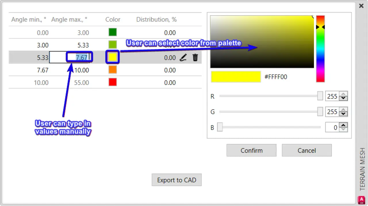
The limit values and colors for each range can also be further fine-tuned directly on the table.
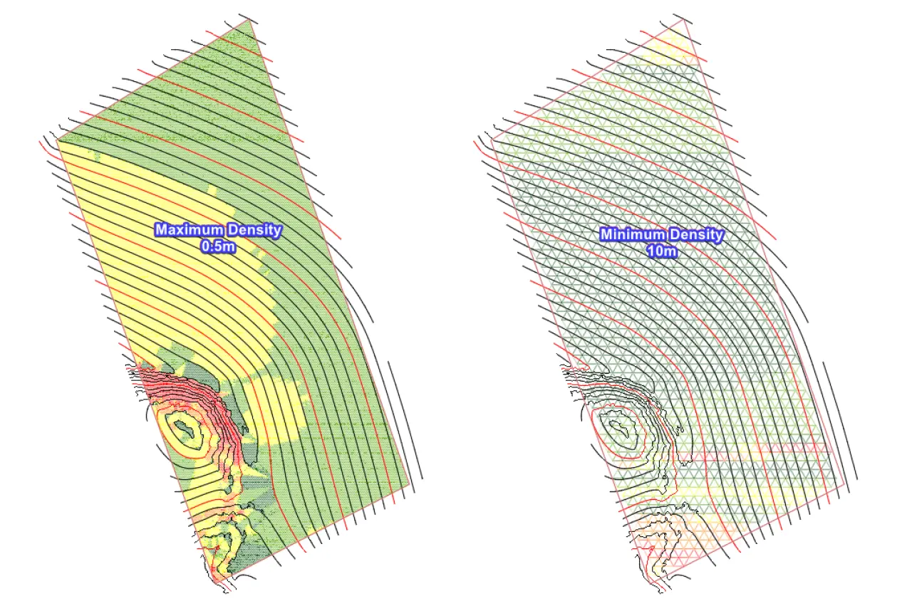
In Mesh settings, the user can modify the mesh density to change the mesh triangle sizes.
Higher density provides more granularity (smaller triangles) but at the expense of slower processing (even with smaller areas it can still take multiple minutes to load).
The most important step when designing a mesh, is to select the adequate Slope direction, in most cases, so it matches the axis of the mounting system that is going to be used. For single axis tracker systems, North-South, North Facing or South Facing would be selected. For Fixed-tilt systems, East-West is most commonly used. There is also the option to select Any Direction, which means the user can follow the slope of the terrain from high to the low point. This can be useful when doing the first assessment of the terrain to decide what the best path is for roads, to check hydrology and define where to place erosion control elements, to decide which mounting system is more adequate for the terrain, or even to evaluate if non-standard azimuth might improve the design.
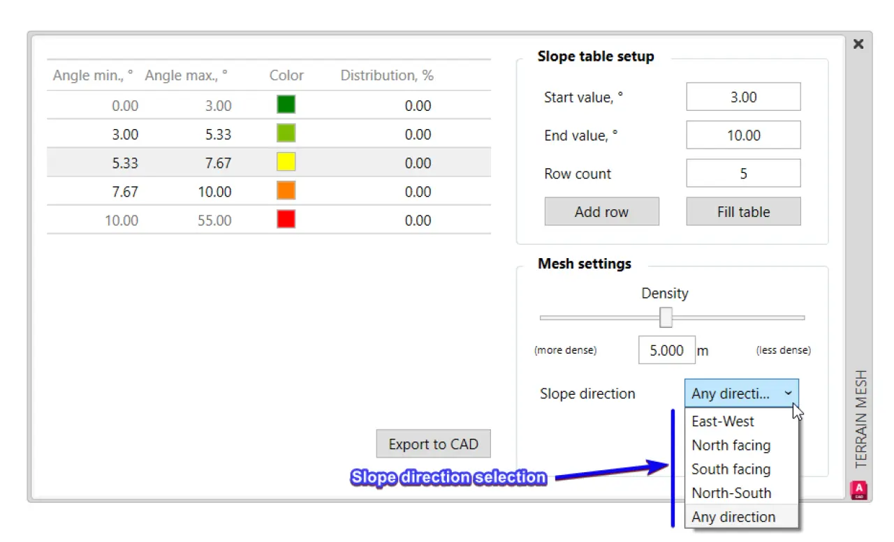
Finally, the Distribution percentages that are displayed enable to estimate what loss of terrain/capacity would occur if certain areas are excluded from frame generation.
2. Checking for topographical layer issues
When selecting a topography, it is advisable to check that none of the elements included are foreign or corrupt objects. These mishaps are common when importing a KML file (tutorial available here) or externally referencing “Xref” terrain (tutorial available here), moreover if it is Point Cloud data.
The Mesh will highlight these issues even when working within a 2D view:
But with a 3D viewport selection, the non-compliant features will become obvious:
Fixes can be then performed, which in many cases require correcting the elevation of faulty contour lines or height points:
3. Creating offsets
When a manufacturer defines limits to the sloping of their mounting system, the Mesh interface can be used to exclude potentially problematic areas from Mesh generation. This can be done by simply adding exclusion zones.
By defining the Mesh ranges with an appropriate tolerance, the user can allow for an acceptable amount of civil works to increase the usable area before excluding sections that will require major ground grading.
In this example, although the manufacturer of the tracker system defined a maximum N-S slope of 12°, the designer selected a 16° offset limit, to allow for subsequent civil grading in between 12° and 16°.
4. Overlapping offsets
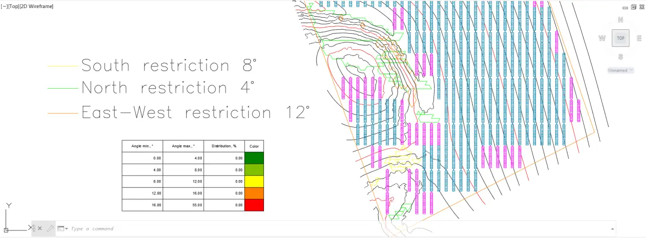
Offsets don’t necessarily need to be selected following only one direction, because when they are generated, even if the Mesh is redone with a different axis, the original exclusion lines remain. The designer can define different limits in different directions, in accordance with the manufacturer's or designer’s specifications.
In this single-axis tracker example, offsets are first set at 8° in the South direction:
Subsequently, at 4° in the North direction:
And lastly, at 12° in the East-West direction:
After defining the exclusion areas which are directly placed in the PVcase Offsets layer, frame generation will avoid all the different restrictions defined:
As seen in these videos, if the user wants to differentiate the exclusions that apply to different directions, the color can be easily changed before generating the new Mesh.
5. Changing offset layer
In some cases, the user might want to delineate areas that might be treacherous, but without excluding them from frame generation altogether. In that case, after creating the Offsets with the Mesh tool, all of them can be selected by right-clicking and selecting similar, in order to move them to a new layer that is not selected in the restriction zone layer list (in Layout Generation Settings).
By using the Slope Analysis tool, the designer can verify which frames are out of range and if they coincide with the “deactivated” Offset areas:
6. Checking shadow frames
When troubleshooting PVcase Shadow Frames or Indicative Frames, it is not always easy to find the root cause for the problematic red/brown frames. One common issue is that the frames are outside the terrain boundaries, even though it might not be obvious from looking at the contour lines or height points.
A mesh will clearly delineate the limits of the terrain that the Ground Mount software is considering, making it easy for the user to see if the questionable frames are outside. Then the issue can be corrected by adding more terrain data or eliminating the faulty frame altogether.
7. Comparing Mesh before and after grading
A generated Mesh always triangulates the topography that has been selected in Layout Generation Settings. Taking this into account, several Meshes can be created to compare different terrain sources (for example Import terrain versus a KML import file) or even to contrast the terrain before and after ground grading (i.e. Existing versus Proposed).
However, a workaround is needed in order to do this, because each time the Generate Mesh option is used, the previous Mesh is discarded. The trick here is to avoid generating the Mesh using the same exact perimeter polyline. Only a duplicate perimeter needs to be created, moved to a different layer, and selected when proceeding to generate a second Mesh.
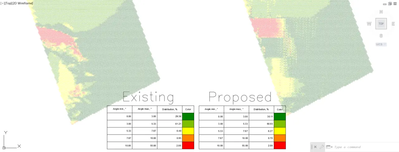
In the following example, Existing versus Proposed terrains will be compared. The first step is to generate the Mesh for the Existing topography (using the PVcase PV area as perimeter) and move it to the side for later comparison:
The second step is to generate the frames on the Existing Terrain, perform Collision Analysis, grade the area to correct collisions and show the Heatmap:
The third step is to create a new polyline that matches the PVcase PV Area (but is not in the PVcase PV Area) and use it to generate the Mesh for the Proposed Terrain:
The last step is to move the new Proposed Mesh next to the Existing Mesh in order to compare them one to one (and with the Heatmap that was also generated):
Also important, is to make sure that the table with distribution % is exported to CAD each time a new mesh is fabricated in this fashion so that quantities before and after grading can be compared:
8. Exporting to PVsyst
Last but not least, the only way to export a terrain to PVsyst is by selecting a Mesh. If the user selects the option to “Export to PVsyst” without a Mesh being available in the drawing, he/she will not be prompted to select a terrain and only the Frames and shading objects will be exported.
Although not necessary, exporting a Mesh to PVsyst can be useful when the designer wants to account for the direct shading of any nearby terrain features (like a hill) when simulating the performance of the power plant.
Note: Generating a Mesh is not necessary when exporting to PVcase Yield, as this tool will intelligently import the terrain layer from PVcase.
Although not necessary, exporting a Mesh to PVsyst can be useful when the designer wants to account for the direct shading of any nearby terrain features (like a hill) when simulating the performance of the power plant.
Here you can find more information specific to exporting to PVsyst for Fixed-tilt frames and Single-axis trackers.