Maximizing rooftop solar potential: a design guide for residential and commercial projects


Rooftop solar is rapidly gaining traction, offering homeowners and businesses a clear path to energy independence, significant cost savings, and a reduced environmental footprint.
This popularity reflects broader industry growth, with residential adoption driven by decreasing costs and attractive incentives — a well-designed residential system can even achieve a 16-20% annual return on investment. Commercial and industrial (C&I) rooftop solar design is also expanding quickly as businesses aim to lower operating costs, meet sustainability goals, and improve their brand image.
However, simply placing panels on a roof isn't enough to realize the full benefits. Maximizing rooftop solar potential hinges on using commercial solar design software to ensure smart, meticulous planning right from the start. This guide will walk you through the essential stages of successful rooftop solar design.
Foundational considerations
Before a single panel is placed, several foundational considerations are crucial for a successful commercial solar project. First, understanding energy needs is paramount. For residential projects, analyzing at least one year of electricity bills (to account for the seasonality of energy use) helps identify consumption patterns and anticipate future additions like EVs. Commercial projects require a deeper dive into the bills of the past few years, factoring in potential increases from electrifying vehicle fleets or expanding operations, to properly size the system.
Even more vital is to assess roof suitability and structural integrity. The roof must bear the solar installation's weight, accounting for snow and debris — structural reinforcement might be necessary. Also, project developers must ensure the system doesn't hinder roof drainage or access for maintenance. Furthermore, they always have to check roof warranty compliance too; in some cases, replacing an aging roof before installation can be a wise choice.
Finally, navigating regulatory compliance and permitting on a local and regional scale is also necessary. Municipal zoning laws and permitting processes vary, impacting timelines and costs. Permitting ensures safe, correct installation. Additionally, developers should be aware of interconnection challenges, including utility requirements or grid constraints, that can affect project approval and timeline.
Key steps in commercial rooftop solar design
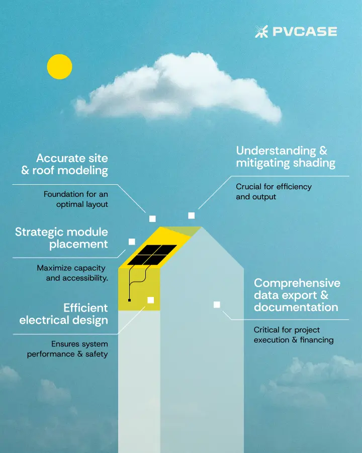
The actual rooftop solar design outlines several critical phases, each building upon the last to create an optimal and efficient installation.
Step 1: Building your digital roof
Precision in roof modeling is the bedrock of successful PV design. Accurate dimensions and a clear understanding of all roof features are vital for an optimal panel layout. Gathering this data often starts with an orthographic photo of the building or its precise dimensions. Tools like PVcase Roof Mount simplify this process, allowing you to import satellite imagery directly into design software.
However, roof modeling can present challenges, especially with complex roof geometries or older buildings lacking accurate blueprints. Beyond basic satellite views, more detailed imagery services like Google Earth Pro, Bing Maps, or high-resolution commercial providers such as Nearmap can provide invaluable data. For detailed C&I design analyses, drone surveys and photogrammetry are increasingly used to capture precise 3D models of properties, revealing every nuance of the roof and its surroundings.
For older structures, structural engineering assessments are crucial to confirm load-bearing capacity. On-site verification and flexible mounting systems further help overcome these hurdles.
Defining elements like parapet height and safety paths within the digital model is essential. This ensures code compliance, meeting mandated setback distances from roof edges and obstructions for safety and access. These clear spaces are critical for fall protection and worker safety during installation and maintenance, and they provide firefighter access in emergencies. Strategic placement also helps minimize wind loads and ensures optimal system performance by reducing shading from parapets.
All this compiled information serves to digitally create the building's perimeter and layout with as much detail as possible. This includes:
Defining architectural elements such as heights, slopes, ridges, and parapets
Identifying all potential obstructions on the roof, like chimneys, skylights, HVAC units, smoke ventilators.
Mapping external elements like trees or adjacent buildings that could cast shadows.
Ensure compliance with industry standards and local building codes, National Electrical Code (NEC) in the US.
Step 2: Mitigating shading losses in efficient commercial roof layouts
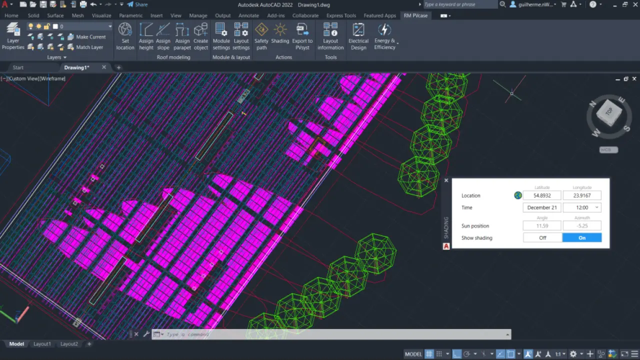
Even partial shadows can drastically reduce solar panel efficiency and overall system output. This makes shading analysis a crucial step, identifying roof areas affected by permanent obstructions (chimneys, HVAC units, nearby buildings) and transient sources (trees, seasonal sun angles). Particularly in the case of vegetation, accounting for its future growth helps ensure long-term efficiency too.
Analyzing hourly solar paths is a key step to address these factors, particularly focusing on peak production hours. Software like PVcase Roof Mount projects shadows based on the time of day and year, allowing engineers to quickly see affected zones before placing modules.
Step 3: Module placement strategies for optimal performance
With a precise roof model and shading analysis complete, the next step is defining PV areas and strategically placing modules. This involves segmenting the roof based on orientation, available space, and shading. Module selection is then based on precise dimensions, including length, width, thickness, and power output.
Several module orientations and mounting types are available.
Fixed-tilt, with a different orientation depending on the hemisphere, and often with a tilt angle corresponding to the latitude, generally maximizes total energy production.
Flat East-West configurations provide a more balanced daily energy profile, capturing morning and afternoon sun. This can be beneficial for specific energy consumption patterns or limited south-facing roof space.
The "V-shape" East-West design can further optimize density.
For aesthetic appeal or simpler installations, flush mount systems place panels parallel to the roof's surface.
Next comes layout optimization, an iterative process. It involves adjusting module arrangements to maximize capacity while accounting for practical needs like maintenance corridors. These corridors are vital for code compliance, providing safe access for installers and maintenance personnel, facilitating emergency response, and ensuring efficient operations and troubleshooting throughout the system's lifespan.
A key step when testing different iterations is to perform shading data analysis to pinpoint the less productive modules (i.e., the ones with greater power losses). The goal is to keep only the highest-performing ones to reach the planned capacity.
After optimizing the layout, the total system capacity can be accurately assessed, contributing to maximizing commercial solar potential.
Your step-by-step guide to C&I rooftop solar efficiency
Download the e-book to:
Improve the accuracy and reliability of your rooftop projects.
Optimize your workflow and make informed decisions.
Cut development time and save costs.
Step 4: Connecting the system
The final key design phase is designing the electrical system to ensure safe and efficient power flow, as well as seamless integration with the grid. This begins with inverter placement, which can be on the roof or inside the building, considering accessibility and realistic cabling routes.
Beyond layout optimization, conducting shading analysis is also useful for selecting the appropriate inverter technology and location.
Traditional string inverters can suffer substantial power loss across an entire string if even one panel is shaded, a "Christmas light effect" where the weakest link limits the whole.
Microinverters operate each panel independently, meaning a shaded panel only affects its own output, preserving the performance of the rest of the array.
Power optimizers offer a hybrid solution, optimizing individual panel output while still using a central string inverter. These Module Level Power Electronics (MLPEs) are highly effective in complex or shaded environments.
The next phase is to string the modules, which involves connecting panels in series, factoring in voltage limits and Maximum Power Point Trackers (MPPTs) on the inverter. Strings are then carefully paired with their inverters, either through basic design or more complex configurations involving multiple strings per inverter or MPPT inputs. Tools like PVcase can color-code inverters for quick visualization of the layout.
Subsequently, the cabling layout has to be created. Planning cable trays or trenches and routing DC cables from modules to inverters along the shortest, most efficient paths minimizes energy loss and ensures safety. The electrical design must also account for rapid shutdown requirements, a critical safety feature mandated by codes like NEC 690.12. These systems quickly de-energize or reduce voltage in the array conductors, allowing emergency responders to safely work on or near the solar system.
Overall electrical design also involves determining power consumption demands to properly size the PV array and any battery storage. Inverter sizing must match the array rating for efficiency, and wiring needs appropriate sizing to minimize voltage drop and ensure overcurrent protection, grounding, and bonding in compliance with all relevant standards.
Finally, developers must select efficient panels (typically 18-24%, monocrystalline often over 20%, or bifacial for increased yield), quality inverters, and MPPT charge controllers. For mounting, options include ballasted or attached racking systems, accounting for about 10% of total system cost.
Step 5: Data export & project documentation
All the meticulous design work culminates in data export and project documentation. This detailed, exportable data is crucial for every subsequent project phase, from procurement and installation to permitting and performance modeling.
A comprehensive Bill of Materials (BOM) should include module quantities, cable lengths, string numbers, and inverter details, streamlining procurement and logistical planning. Additionally, CAD or layout exports provide essential visual documentation for construction teams and permitting authorities, ensuring a smooth transition from design to reality.
Optimizing rooftop design with PVcase Roof Mount
While this guide outlines best practices, achieving them efficiently demands advanced tools. PVcase Roof Mount streamlines your workflow, allowing rapid creation of complex roof models and quick identification of shaded areas to optimize layouts and avoid inter-row shading. It simplifies flexible module placement, including maintenance corridors, and integrates electrical design for realistic inverter placement and automated cabling.
Moreover, the software also generates detailed BOMs and exports to PVsyst, saving significant time—one user reported reducing a 1 MW project design from two weeks to a single morning. Ultimately, PVcase Roof Mount delivers the precision, cost-savings, and informed decisions essential for successful commercial rooftop solar design.
Achieving peak potential with smart design
Maximizing commercial solar potential hinges on a meticulous design process, from precise roof modeling to integrated electrical layouts. This early, detailed design ensures more efficient, cost-effective, and higher-performing systems. PVcase Roof Mount empowers solar developers with the advanced automation and precision needed to optimize the C&I rooftop design process from day one.


Maximize the potential of your rooftop C&I projects
Book a demo and learn to optimize layout efficiency and streamline rooftop solar design with cutting-edge software.