CAD solar system design software - advanced solutions for PV projects

How to select the right native CAD solar system platform for your next commercial, industrial, or utility-scale project.

3D illustration of the layout of a utility-scale solar power plant on PVcase Ground Mount.

What is CAD solar system design?

CAD solar system design has evolved from a drafting exercise into a high-fidelity engineering workflow, allowing for more efficient planning, minimizing the risk of human error, and facilitating advanced simulations that would have otherwise been impossible. The result is a streamlined workflow that allows developers, engineers, and other stakeholders to build smarter, faster, and more ambitious projects than ever before.

Why choose CAD solar design software?

CAD solar design systems provide engineering teams with the speed, accuracy, and control needed to deliver industry-leading PV solutions at scale.

Enhanced precision and accuracy

Solar CAD software ensures centimeter-level precision and automates complex calculations to minimize risk. By leveraging real-world data, it optimizes uneven terrains and enables rapid iterations for maximum space efficiency.

Increased efficiency and speed

Solar CAD systems accelerate development by 90% by automating layouts and complex analysis. This streamlines workflows, improves stakeholder coordination, and allows engineering teams to focus on high-value innovation over manual tasks.

Risk mitigation

CAD software reduces uncertainty by merging site data into a unified view. By identifying constraints and automating collision analysis early, it prevents installation obstacles and slashes grading costs through intelligent topography mapping.

Competitive advantage

Solar CAD transforms data into 3D visualizations and precise Bills of Materials, boosting stakeholder confidence. This streamlines collaboration and enables aggressive, high-ROI bids by translating complex engineering into "ready-to-build" visions.

Cost optimization

Solar CAD aligns structural precision with resource transparency to cut costs. By mapping frames to topography and optimizing electrical layouts, it minimizes cable losses and converts CAPEX estimation into a precise roadmap.

Solar system CAD drawing process

The drawing process is streamlined with an integrated CAD solar workflow that moves uninterrupted from early-stage site analysis to completed documentation.

Design

Once a suitable site has been validated, focus can turn to design. By utilizing a purpose-built CAD solar environment, engineers can automate much of the early stages of development. That includes automating the generation of thousands of layout variants to find the optimal GCR while simultaneously producing an accurate Bill of Materials (BoM).

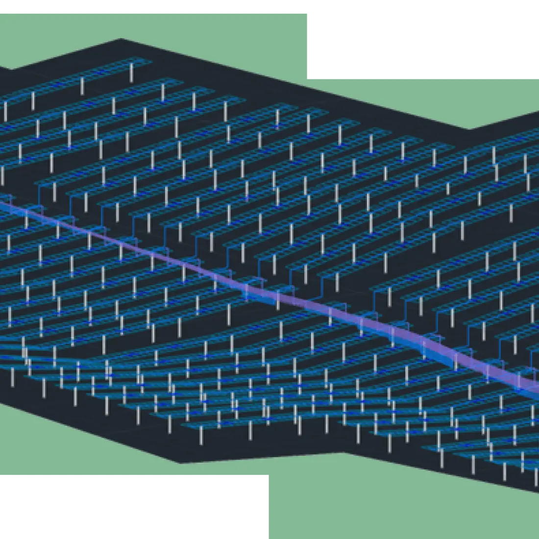
Detailed mechanical design and analysis:

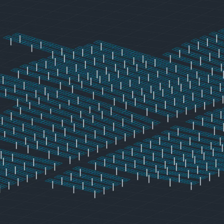
  • Piling and collision analysis: Detect and eliminate potential installation obstacles in the layout—a critical step for mitigating construction risk and obtaining construction-ready piling data.

  • Ground grading optimization: Optimize the placement of PV frames to minimize the need for extensive and costly ground grading work.

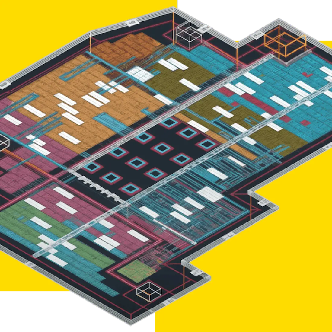
Precision electrical design:

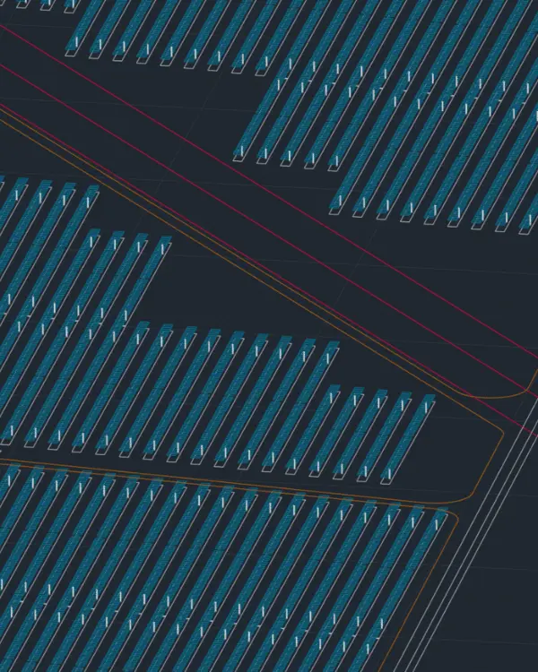
  • Automated device placement: Automatically place major electrical components like transformers and central inverters for optimal system performance and minimal cable losses.

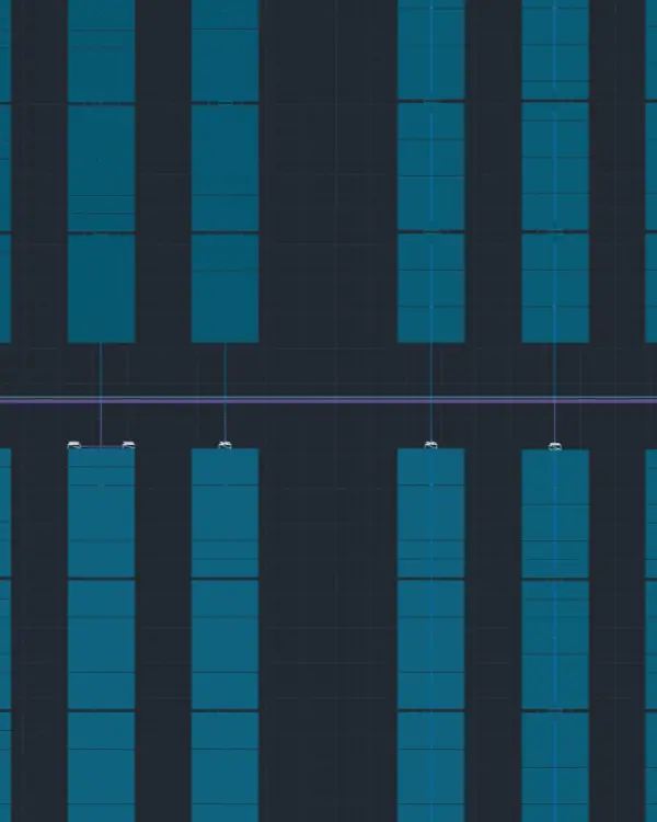
  • Comprehensive 3D cabling visualization: Visualize the complete electrical design in 3D to streamline planning and reduce cable-related errors.

Solar-plus-storage design:

  • BESS integration: Design and optimize both AC-coupled and DC-coupled Battery Energy Storage Systems (BESS), including their electrical layout and ground grading requirements.

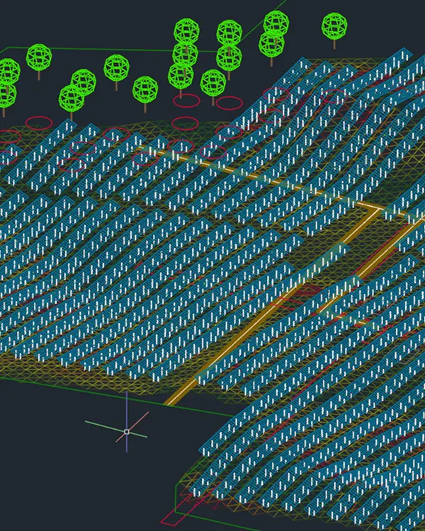
At this point, the CAD environment becomes the foundation for advanced modeling, slope, and shading analysis—offering a controlled space in which variables can be checked before moving to construction documentation.

Construction documentation

Once the topographical-aware design is finalized, engineers can instantly export precise Bill of Materials, 3D scenes, and ISO-aligned capacity reports for stakeholders to facilitate faster approvals, while PV consultants can better support their clients with customizable analysis, data visualization tools, and compelling insights.

  • Detailed Bills of Materials (BOMs): Comprehensive material lists for accurate procurement and cost estimation

  • Detailed terrain information: Export terrain data and grading requirements for construction planning

  • PVsyst-compatible data: Generate simulation-ready files for accurate yield analysis and energy modeling

These outputs – along with detailed electrical drawings and installation guidelines – can all be automatically generated based on the finalized design.

Solar CAD software selection criteria

Scalability and performance

Project size handling: Versatile solar CAD software adapts to any scale, from smaller C&I rooftop systems to utility-scale ground-mounted projects.

High-volume data processing: By processing high-volume terrain data and restriction layers, these platforms achieve millimeter-level precision on challenging topographies.

Performance optimization: This high-performance infrastructure automates labor-intensive tasks like cable routing and shading analysis, saving hundreds of development hours while ensuring that complex project requirements are met with speed and technical accuracy.

Integration capabilities

Third-party software compatibility: Effective solar CAD platforms ensure uninterrupted workflows through seamless integration with existing GIS, financial, and AutoCAD environments.

Data export/import functions: Open-source capabilities eliminate redundant data entry, while robust import/export functions allow teams to easily incorporate terrain surveys and share detailed reports with stakeholders.

Workflow integration: Shared project environments foster real-time cross-disciplinary collaboration. By utilizing version control and access validation protocols, these systems maintain high data integrity and security.

Solar CAD design features and capabilities

Purpose-built CAD solar platforms take the flexibility of CAD and place it within a solar-first environment that allows for tailored modeling, automated processes, and standardized design approaches.

Trusted by industry leaders

Industry applications and use cases

Solar CAD software is being used today to support a wide range of PV projects, adapting to the unique challenges of everything from commercial rooftops to utility-scale power plants.  

Utility-scale solar projects

CAD software is vital for utility-scale solar, managing massive footprints across complex landscapes with precision. Integration allows for automated modeling that minimizes ecological disruption and groundwork.

By automating cabling and grid tie-ins, developers save hundreds of planning hours and significantly reduce CAPEX costs, ensuring detailed accuracy while preventing expensive construction delays in large-scale developments.

Commercial and industrial applications

Commercial and industrial roof-mounted systems can require an even higher, millimeter-perfect level of precision. Rooftop installations come with unique practical challenges, including irregular deployment spaces, HVAC equipment, and skylights. In addition, there are typically strict fire and safety regulations to be considered.

Engineers can design and work on an exact replica of the target rooftop within a CAD solar environment, while seamlessly adding interaction layers from structural considerations to interconnection points and safety pathways.

The result is a smoother permitting process, fewer revisions, and a design package customers can trust.

AutoCAD solar integration - industry standard

As the industry standardizes around CAD-based engineering, PVcase is leading the way in native AutoCAD software designed specifically for solar development.

PVCase Ground Mount - AutoCAD-based solution

PVcase is a purpose-made solar environment built directly on the AutoCAD platform, allowing engineers to maintain the familiarity of CAD while gaining access to powerful solar-specific functions. 

For those who adopt an AutoCAD engineering process powered by PVcase Ground Mount, the improvements are substantial: an 80% reduction in design cycles and 50% faster project delivery, in one case study.

Designed for mid-to-utility-scale projects, PVcase Ground Mount expedites development cycles and accelerates ROI.

PVcase Ground Mount 3D layout of utility-scale solar rows

PVCase Roof Mount – AutoCAD-based solution for rooftop solar

PVcase Roof Mount provides an AutoCAD-native solution specifically for commercial and industrial solar challenges.

By leveraging smart algorithms, it automates layout generation to reduce design time by 85% and streamlines critical tasks like cable routing and shading analysis. This precision in mechanical and electrical design minimizes risk while eliminating manual errors.

Ultimately, the software enables teams to scale project delivery, transforming rooftop potential into "ready-to-build" assets with unprecedented speed and technical accuracy.

High-performance solar development workflow

PVcase enables engineering teams to generate professional-grade outputs, including slope-aware mechanical layouts, automated cabling plans, and comprehensive Bills of Materials (BOM). To ensure regulatory compliance and financial viability, the platform automates the production of Single Line Diagrams (SLDs) and utilizes physics-based modeling for highly accurate energy yield simulations.

This interoperability with industry standards like PVsyst ensures that projects are not only technically sound but also bankable and ready for immediate implementation.

background imagebackground image

Solar that sees the light of day

Turn complexity into clarity and confidently move your solar project forward.

CAD solar system FAQS