PVcase Ground Mount tool has a new functionality allowing it to work with terrain-following trackers. Recently we organized a webinar on the feature hosted by Guy Atherton, PVcase Ground Mount Product Manager. Below we give you the answers to the most frequently asked webinar questions, that we hope will shed more light on how to optimally deploy our new feature.
How does the terrain-following tracker function impact PVsyst simulations? How should we include mismatch losses?
PVsyst will interpret each of those sections as a separate orientation, so the number of orientations in your PVsyst simulation will be large. Moreover, our PVcase Yield tool takes orientations into account much more quickly and easily, so you should be fine in this case.
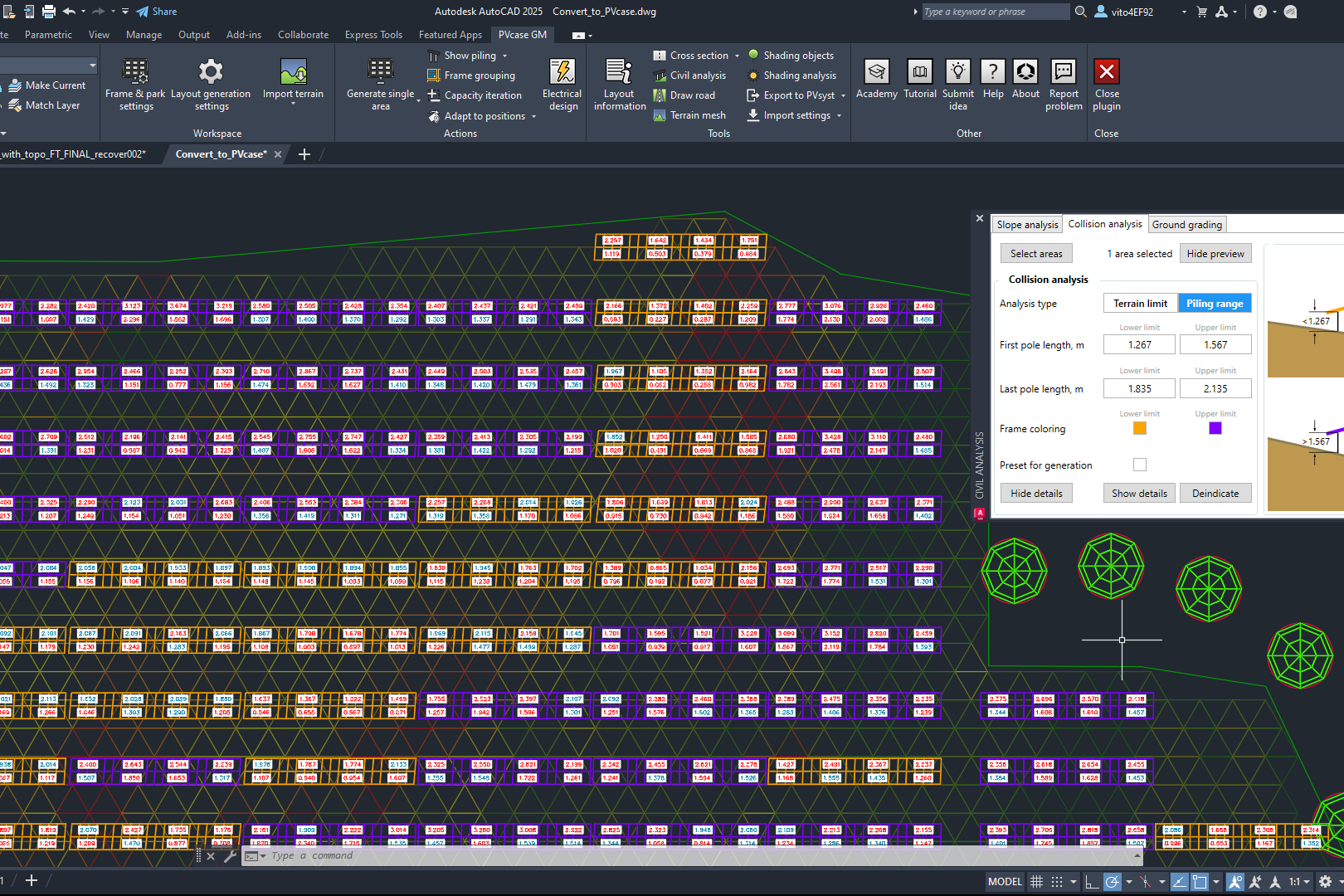
In the orange rows, where the terrain-following tracker hits the joint angle limitation, isn’t it better to account for grading rather than thinking of customizing another tracker?
It’s an option, and that is up to the user. Users can do this if they like. You can select the affected table and just run grading under those tables if you want. We try to make it as flexible as possible.
Does the ground grading consider east-west slopes for axial trackers?
No, the ground grading will just go between the trackers regardless of the east-west slope. However, if there is a corridor, road, or blocked area between the tracker frames, this will not be graded.
How can you solve different heights between different trackers in the same row when setting slope limits and grading?
If you position the trackers with the generation, they will be at the same height. If you’ve done some adapted terrain with different heights, then you can have different heights between the trackers. And if you do set the slope, it will reassign the frame angles and also the heights. So the set slope function gets rid of all of those individual heights.
However, if you change all the heights of the trackers and then do grading, the grading won’t change the tracker positions again. It will grade according to the height range that you specified in the Ground grading interface.
How do these trackers adjust to undulating terrain and a breakline slope change?
The frames are placed like small Single-axis tracker frames. So, the ends of the Frame sections that are placed with the given Frame reveal height. This means that if you have the poles at the joints, the poles will all have the same length. So if there is an undulation or breakline, the smaller Frame section will span over it. With regards to the terrain slope limitations, whatever the manufacturer has in their specifications, you can input it into our tool. We are working with as many manufacturers as possible to ensure it’s working with their systems, so once they have a product available, you can use it in our design tool.
Is it possible to export the surface after ground grading?
We do have a beta function, which allows us to export the points of the surface. We can only export the points because we don’t work with AutoCAD civil surfaces and are not an AutoCAD civil plugin. So you can export every single proposed (Ground grading) point. It’s quite detailed, so whatever detail you put in your existing terrain, it’s modified with our ground grading tool, and you can export that with these export points. Then you will have a .csv file, which you can import into the civil or generate as another surface. That’s about the best we can do now regarding the export of the accurate ground-graded surface.
Do you plan to incorporate the proposed terrain as a surface and make a surface comparison?
It depends on how you want to compare. We have the heatmap, which compares the existing and proposed surfaces graphically. We have the spot levels, which allow you to put actual points that tell you the difference between the two surfaces. We also have the export points, which export the .csv of the proposed terrain. So the comparison we have at the moment is limited to the heatmap and spot levels. You can also compare surfaces in the section view and front view in AutoCAD. Otherwise, you have to use another surface-based tool, such as AutoCAD Civil3d.
Did PVcase validate the terrain-following modeling with tracker manufacturers?
Yes, we have been doing interviews and beta testing with tracker manufacturers. There will be more info on that in the coming weeks.
What is the difference between the “adapt the terrain” option to the “single-axis terrain-following tracker” function?
The “adapt the terrain” function is useful if you move some frames around in the area and want to make sure that they are sitting back properly on the terrain, whereas the “single-axis terrain-following tracker” function is for generating the tracker following the terrain. So “adapt the terrain” is something you do after you have already generated a layout, and you want to modify your layout. Whereas what we were showing today is part of the generation feature, which is the first thing you do when you put your frames into the field.
What is the density of the points of the proposed surface?
For the proposed surface, we place exterior points on the outer module corners, and on each of the poles under the frame. Everywhere else, we keep the density of the points of your existing terrain.
Try the new terrain-following trackers’ feature. Schedule a demo now!

You might also be interested in:
Siting of PV power plants. How to adapt solar designs to complex terrains?
Choosing the wrong PV project site lowers energy output, raises costs, and risks legal issues. PVcase offers solutions. Discover them by reading the article.
Overcoming technical challenges in renewable energy projects. How PVcase transformed OHLA’s design process
Explore how OHLA overcame renewable energy design challenges with PVcase, streamlining solar park operations and achieving remarkable business growth.

Bridging the renewable energy skills gap. A success story of PVcase, Enery, and the University of Applied Sciences Upper Austria
Discover how PVcase, Enery, and the University of Applied Sciences Upper Austria have collaborated to prepare future solar engineers through an innovative educational initiative,…
Top 10 questions from Intersolar Europe 2024, answered
Get answers to the top 10 questions asked during Intersolar Europe 2024 that cover PVcase Prospect's availability, integration of PVcase products, and much more. Your question is…
Targeted solar marketing for successful landowner outreach — e-book included!
Discover how innovative strategies and Anderson Optimization's GIS Site Selection can boost solar outreach ROI and conversions. Download the ebook for more insights!
PVcase is part of the 42-month long SUPERNOVA project
PVcase, together with 19 partners from all over the world, is part of the 42-month SUPERNOVA project, focusing on O&M and grid-friendly solutions for reliable, bankable, and…
PVcase tools are now compatible with AutoCAD 2025!
We’re happy to announce that you can now use PVcase Ground Mound and Roof Mount, our flagship CAD-based tools, on AutoCAD 2025, enjoy its multiple functionalities and integrate…
PVcase is the finalist of “The smarter E AWARD” in the Photovoltaics category
We’re the finalists of “The Smarter E AWARD”! Read more about the nomination and dive into the PVcase Integrated Product Suite offering that innovates the industry.
Making great designs on good sites—the importance of topo data for PV design
Topo data is the first step in determining the success of your solar project. While the terrain is crucial in this regard, developers should also consider grid connectivity and…

How policy can shape future solar energy expansion
Policymakers and regulatory organizations must actively support solar power's growth and renewable energy advancement. Read the article to learn how.
Shading Analysis: advanced feature for C&I roof-mount solar projects is live
Shading Analysis is live! Read the article to learn about benefits, capabilities of the tool, and how it can help users and decision-makers.
PVcase wins the BNEF Pioneer Award 2024 for innovative solar design solutions
We won the prestigious 2024 BNEF Pioneers Award! Find out how our software contributes to relieving bottlenecks in the deployment of clean power.
Sustainable cities: what urban living of the future might look like
From clean energy to green bonds and renewable energy stocks, there are many ways you can invest your money in a sustainable future. Find them out by reading the article.

8 ways to invest your money in a sustainable future
From clean energy to green bonds and renewable energy stocks, there are many ways you can invest your money in a sustainable future. Find them out by reading the article.

8 business opportunities in renewable energy
There are many potentially lucrative business opportunities in renewable energy. Learn how you can use these opportunities to make money while contributing to the green…