Digital technologies have contributed a great deal to the solar engineering industry. Hand calculation for shading angles, Excel sheets, estimating project cost by historical data, and non-site-specific solutions are all past.
Below Sophie Nguyen, Senior Technical Support Engineer at PVcase, shares her experience in the development of solar engineering and the constant progress of solar design tools.
What is your earliest experience of solar engineering design methods?
We used to do land due diligence differently — you had to go to the state institutions to pull infomation for land search, estimate project size by experience or guessing, and use that info for project financing. Then, we used to design on flat terrain and modify the design once the site survey returned.
It took longer to redesign projects to fit the terrain information, deviate engineering risks for site-specific projects, and do calculations using Excel sheets. Despite going through heavy manual engineering work, a lot of onsite revision caused project delays or increased project cost that was not anticipated during project development.
How did the software tools change over time?
Before all those smart tools emerged, most designs were done in AutoCAD or Civil 3D. You had to manually create all the blocks within AutoCAD and then use such automation tools as the Dynamic Block or the good old copy/paste. You also had to do a lot of geometrical calculations manually and then put it in AutoCAD.
When designers started to consider other issues and requirements like terrain, drainage, and roads, they began to utilize Civil 3D tools because more projects required ground grading and other civil engineering aspects. They also started employing 3D elements instead of just a flat 2D plan. Engineers still had to do cut-and-fill manually within AutoCAD civil 3D, which is harder to comprehend if you’re not a civil engineer.
In addition, Civil 3D is more difficult to use and more expensive compared to the regular AutoCAD. If you did a solar design, you had to consider many details in planning, but there was no comprehensive single tool that designers could use.
Later on, applications like Aurora Solar and Helioscope started to emerge. And that was when you had the integration from the sales standpoint. When they started, reports were only in PDF format because they were more focused on the initial sale design and one-click generation of the quote instead of engineering focus. Later on, software developers figured out that the workflow must be integrated from the sale to design engineer and then through permitting. That was when they started to implement features allowing export data to a DWG or DXF file.
As a result, the layout generated within Aurora or Helioscope could be exported and imported back into AutoCAD. However, once file is exported to AutoCAD designers had to clean up the design, connect the lines and dots before proceeding with the design.

How did PVcase tools improve engineering processes?
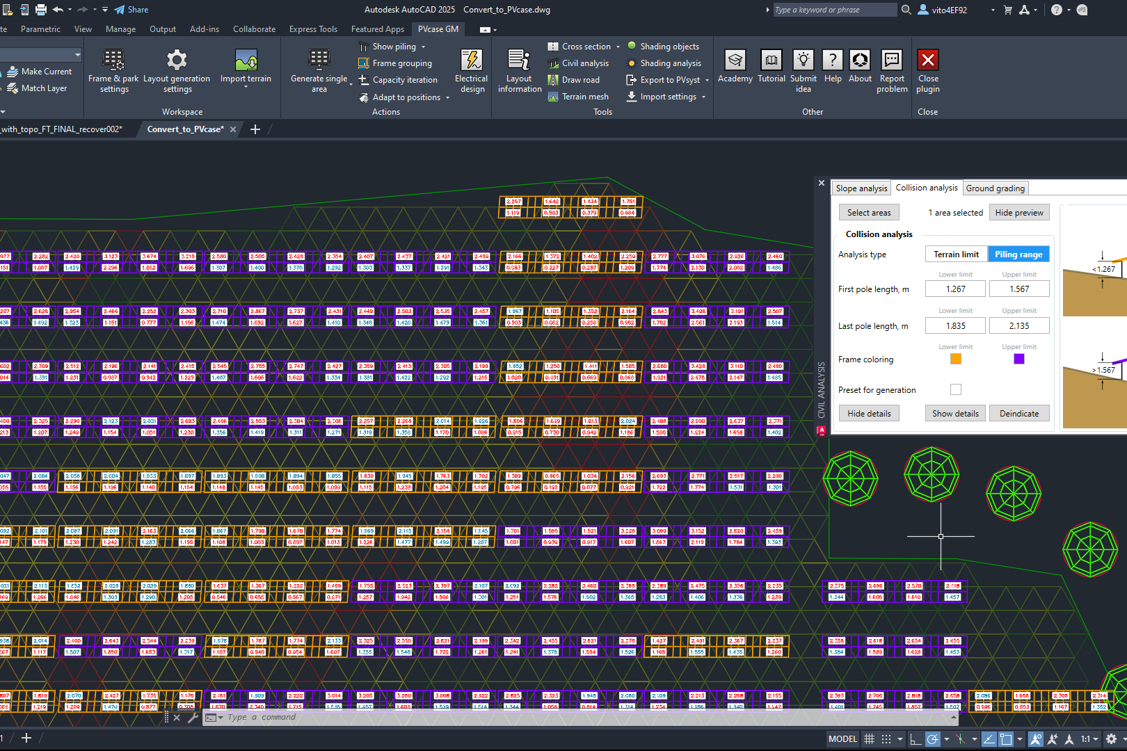
With PVcase, the blocks are generated when we execute a command, and instead of line segments, everything is joined together. Then, PVcase can automatically put each element on different layers within AutoCAD. So a user doesn’t have to select it and manually put it on a layer.
Users no longer have to calculate the spacing between the frames because all you have to do is put in the project location. Then, PVcase automatically calculates the frames’ pitch and spacing for you, so you don’t have to do that manually. Before, you had to figure out the location, and then you had to search for the sun location., and on top of that, you had to calculate the coordinates. Afterward, you had to do the geometrical calculations of the Sun array that hits your module and its shading. Later on, you could use geometrical calculations to calculate the pitches. So, automating that alone, PVcase takes out the human error part.
Designers can spend a day instead of a week or two on a design with all the automation tools. For the electrical part, you have to complete your design more accurately, meaning users have to define the route of the cable and the place of electrical equipment. However, after completing electrical design using PVcase, labels and numbers are being automated, making it more convenient for design engineers to present data to their clients. In addition, users get a detailed BOM, which includes all the precise cable lengths. Electrical engineers can then use BOM to calculate wire size or voltage drops.
Also, the 3D elements of PVcase tools show the distance from the frame to the ground and generate a quick profile cut through the frame to analyze specific segments. Depending on the terrain, it might be different from frame to frame. So, PVcase tools give you an accurate model instead of approximate assumptions.
Moreover, PVcase also presents a couple of new tools:
– Anderson Optimization provides users with a smooth integration from project development to engineering. It helps to reduce risks, keep the project on schedule, and increase financial accuracy.
– PVcase Yield accurately calculates energy production and helps with project financing and site feasibility estimations. It can help identify the site’s problematic issues and reduce future operational risks.
All the recent developments could sound like a distant dream 20 years ago. But what is the future of digital solar engineering?
We will have more accurate, site-specific solutions and more streamlined & automatic processes for development, financing, design engineering, and project management. For example, Anderson Optimization can be used in development, PVcase for design engineering, and Yield can be incorporated to make financial decisions. Eventually, all three platforms will be integrated and streamlined into one process.
You might also be interested in:

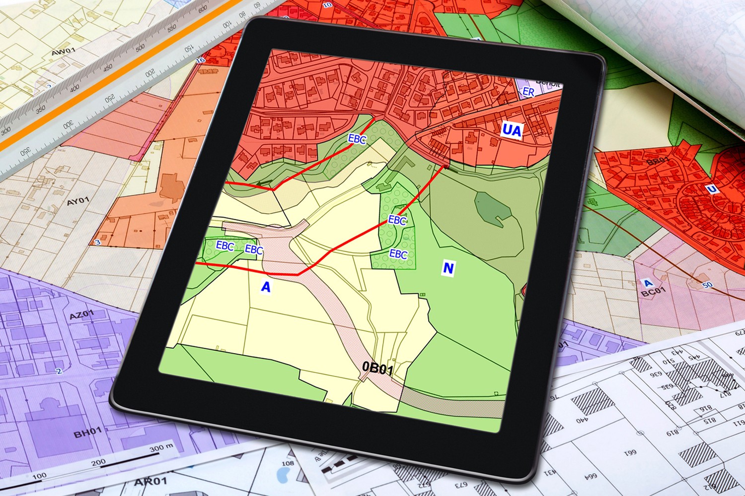
Siting of PV power plants. How to adapt solar designs to complex terrains?
Choosing the wrong PV project site lowers energy output, raises costs, and risks legal issues. PVcase offers solutions. Discover them by reading the article.
Overcoming technical challenges in renewable energy projects. How PVcase transformed OHLA’s design process
Explore how OHLA overcame renewable energy design challenges with PVcase, streamlining solar park operations and achieving remarkable business growth.

Bridging the renewable energy skills gap. A success story of PVcase, Enery, and the University of Applied Sciences Upper Austria
Discover how PVcase, Enery, and the University of Applied Sciences Upper Austria have collaborated to prepare future solar engineers through an innovative educational initiative,…
Top 10 questions from Intersolar Europe 2024, answered
Get answers to the top 10 questions asked during Intersolar Europe 2024 that cover PVcase Prospect's availability, integration of PVcase products, and much more. Your question is…
Targeted solar marketing for successful landowner outreach — e-book included!
Discover how innovative strategies and Anderson Optimization's GIS Site Selection can boost solar outreach ROI and conversions. Download the ebook for more insights!
PVcase is part of the 42-month long SUPERNOVA project
PVcase, together with 19 partners from all over the world, is part of the 42-month SUPERNOVA project, focusing on O&M and grid-friendly solutions for reliable, bankable, and…
PVcase tools are now compatible with AutoCAD 2025!
We’re happy to announce that you can now use PVcase Ground Mound and Roof Mount, our flagship CAD-based tools, on AutoCAD 2025, enjoy its multiple functionalities and integrate…
PVcase is the finalist of “The smarter E AWARD” in the Photovoltaics category
We’re the finalists of “The Smarter E AWARD”! Read more about the nomination and dive into the PVcase Integrated Product Suite offering that innovates the industry.
Making great designs on good sites—the importance of topo data for PV design
Topo data is the first step in determining the success of your solar project. While the terrain is crucial in this regard, developers should also consider grid connectivity and…

How policy can shape future solar energy expansion
Policymakers and regulatory organizations must actively support solar power's growth and renewable energy advancement. Read the article to learn how.
Shading Analysis: advanced feature for C&I roof-mount solar projects is live
Shading Analysis is live! Read the article to learn about benefits, capabilities of the tool, and how it can help users and decision-makers.
PVcase wins the BNEF Pioneer Award 2024 for innovative solar design solutions
We won the prestigious 2024 BNEF Pioneers Award! Find out how our software contributes to relieving bottlenecks in the deployment of clean power.
Sustainable cities: what urban living of the future might look like
From clean energy to green bonds and renewable energy stocks, there are many ways you can invest your money in a sustainable future. Find them out by reading the article.
8 ways to invest your money in a sustainable future
From clean energy to green bonds and renewable energy stocks, there are many ways you can invest your money in a sustainable future. Find them out by reading the article.

8 business opportunities in renewable energy
There are many potentially lucrative business opportunities in renewable energy. Learn how you can use these opportunities to make money while contributing to the green…